EN
EN  DE
DE  ES
ES  FR
FR  PT
PT  RU
RU 
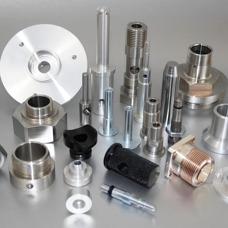
Machinists successfully process aluminum on CNC engraving and milling machines by using short, single-flute carbide end mills, secure workpiece clamping, and appropriate feed and cutting speeds. Friction generated during cutting rapidly produces heat, causing the aluminum to melt and adhere to the tool; prompt chip removal effectively prevents tool damage.
Key Takeaways
- Single-flute carbide bits clear metal shavings quickly and keep the aluminum from melting.
- Carefully set speeds and smart cutting routes keep machines stable and guard your tools from damage.
- Steady streams of air push hot metal bits away to keep tools from getting sticky and prevent surface damage.
Tooling and Setup to Cut Aluminum on CNC
Selecting Single-Flute Bits and Workholding
Picking the correct cutter is the key first step to shape aluminum easily. Strong carbide bits with one cutting edge feature a wide open channel. This extra space throws metal pieces out fast and stops heat buildup.
- Single-flute: Works best for thin walls and quick cuts where fast chip removal stops melting.
- Two-flute: Great for deep hollow cuts that need plenty of room to clear out shavings.
- Three-flute: Works best for basic cutting because it offers steady support and smooth surfaces.
Securing the metal correctly keeps the piece from shifting while you work. Operators pick different holding setups to stop shaking and keep parts from bending out of shape:
| Setup Method | Key Feature | Vibration Benefit |
|---|---|---|
| Vacuum Chucks | Spreads clamping pressure evenly across smooth flat metal sheets | Stops small movements that cause rough cuts |
| Custom Wax Beds | Cheap setup method that sets parts inside carved wax blocks | Holds the bottom of the piece steady |
| Temporary Rib Supports | Built-in metal braces that you cut off after finishing | Keeps thin metal walls from bending inward |
Coating Selection and Rigidity Requirements
Selecting the appropriate tool coating prevents softer aluminum materials from adhering to the cutting tool. End mills featuring a zirconium nitride (ZrN) coating—such as 1/8-inch single-flute cutters—effectively reduce friction during high-speed machining. This smooth ZrN coating maintains low-friction characteristics even at high temperatures and prevents the gummy metal from bonding to the tool surface.
A stable machine configuration ensures that the CNC engraving and milling machine maintains precision throughout the cutting process. Inserting a short tool deeply into the collet effectively prevents tool runout.
Feeds, Speeds, and Toolpaths for Cutting Aluminum
Calculating SFM (Surface Cutting Speed) and Feed Per Tooth
Specialized calculation tools can determine the optimal feed rate and spindle speed based on SFM (surface feet per minute) and chip size settings. When machining 6061-T6 aluminum with solid carbide tools, maintaining an SFM between 800 and 1,500 yields the best results. Operators can calculate spindle speed using a simple formula: RPM = SFM × 3.82 / Tool Diameter. For example, when cutting 6061-T6 aluminum with a 0.125-inch diameter, two-flute carbide tool at 10,000 RPM and a depth of cut of 0.04 inches, the feed rate can be set to 20 inches per minute.
Operators can determine the ideal feed rate using a basic mathematical formula: Feed Rate = RPM × Number of Flutes × Feed Per Tooth. Generating sufficiently large chips helps carry heat away with the metal chips, preventing heat buildup on the tool. This method of heat dissipation protects the cutting edge and prevents the workpiece from overheating. If the feed rate is too slow, the tool will rub aggressively against the metal, leading to rapid tool failure.
Maintaining an appropriate feed rate is crucial; because aluminum is relatively soft, an excessively slow feed rate can cause the material to spring back and rub against the tool, preventing a clean cut.
Applying Adaptive Helical Entry and Shallow Cut Strategies
When machining aluminum on CNC engravers or milling machines, smart toolpath selection helps manage high temperatures. Operators should avoid plunging the tool vertically into the metal, as the resulting impact force causes excessive heat buildup at the tool tip. Instead, using a smooth helical path distributes pressure, allowing the tool to enter the material smoothly.
Adaptive toolpaths maintain a constant tool load, thereby reducing friction during deep cuts. This intelligent cutting method combines shallow lateral cuts with greater depths of cut to preserve tool geometry. Operators should consult typical depth-of-cut values based on specific machining conditions to balance stress and ensure smooth chip evacuation.
Light finishing cuts produce smooth edges on the finished product, preventing the formation of rough burrs. Professional machine shops often combine rapid roughing with light finishing to achieve efficient material removal. Operators adjust cutting parameters for each unique tool geometry to ensure a seamless machining process for clients across various industries. Controlled CNC machining not only extends the service life of carbide tools but also meets the demand for high-quality components in large-scale commercial orders. Optimized tool paths eliminate severe vibrations that can occur during high-speed machining, while precise machine movements prevent metal deformation, ensuring that every manufactured component meets exact dimensional specifications.
Cooling and Chip Evacuation in CNC Machining
Using Air Blast and Minimum Quantity Lubrication (MQL) Systems
When machining aluminum on automated equipment, using compressed air to clear chips is crucial. Operators aim air nozzles at the tool tip to blow away hot metal chips. Specialized Minimum Quantity Lubrication (MQL) systems—essentially spray systems—dispense a fine oil mist; this lubricates high-speed cutting tools while preventing the accumulation of cutting fluid that could soil the worktable.
Air blast and spray units reduce friction during high-speed machining, thereby protecting the cutting tools. A factory producing custom aluminum parts uses a steady airflow to clear chips from deep holes; operators position the air nozzle close to the tool tip to ensure a continuous, uninterrupted stream of air.
Preventing Chip Re-cutting and Built-Up Edge (BUE) Formation
Promptly removing metal waste prevents loose chips from being drawn underneath the rotating tool during heavy-load machining. Machinists ensure a minimum depth of cut of 0.002 inches so that heat is dissipated along with the chips. Limiting the depth of cut to within one-quarter of the tool diameter helps maintain chip integrity, simplifying cleanup. A strong airflow can blow away tiny chips before they melt and adhere to the tool.
Poor chip evacuation leads to the accumulation and adhesion of metal debris, which can damage the tool or even result in the entire workpiece being scrapped. The table below lists the serious problems that can arise when metal debris is not cleared away:
| Consequence | Mechanism | Strategy |
|---|---|---|
| Surface Scratches | Chips are recut into workpiece. | Use air blasts to flush chips away. |
| Smearing | Results from unstable friction. | Apply mist directly at the cut. |
| Dimensional Drift | Welded material alters geometry. | Maintain aggressive feed rates. |
Sticky metal buildup destroys precision cuts on your CNC machine setup. Trapped metal pieces can suddenly make a smooth surface look really rough and messy. Leaving stuck metal unchecked can ruin part sizes, turning a 50.00 mm shaft into 49.80 mm. Sharp bit shapes reduce rubbing to keep tools from breaking down.
Before each machining operation, the operator performs a quick pre-start check: verifying the single-edge tool, checking the pressure of the minimum quantity lubrication (MIST) system, confirming the adaptive ramping toolpath, and securing the workholding device. High-quality surface finishes on the machined parts are ensured through the use of appropriate tool geometry, high feed rates, and air-blast chip evacuation. Before actual aluminum cutting begins, the machine operator runs a dry-run test of the toolpath.
FAQ
Why are single-flute cutters best suited for machining aluminum?
Single-flute cutters feature wide chip evacuation channels that allow metal chips to be cleared away easily. Rapid chip removal helps prevent heat buildup and stops the soft metal from melting and adhering to the cutting edge.
How do operators prevent chip adhesion during machining?
Operators use continuous airflow and minimum quantity lubrication (MQL) sprays to keep the tool lubricated. Moving the tool rapidly also helps dissipate heat by carrying it away along with the chips.
What options are available for high-volume custom production?
Manufacturing partners like KEMING possess high-tech, precision CNC milling equipment. Their automated facilities are capable of producing durable components that meet rigorous global quality standards.