Precision casting design begins with a deep understanding of the process. Good designers intervene early to prevent errors. Many teams struggle with maintaining dimensional accuracy. They also expect smooth surfaces and consistent material every time. Sometimes, poor communication between the foundry and the customer leads to lead times. Some customers are concerned due to a lack of trust in the precision casting process. Casting novices may not anticipate mold costs. KEMING provides advice and full assistance to its clients.
Key Takeaways
- Understand the investment casting process to avoid errors and manufacture high-quality parts.
- Choose the appropriate wall thickness to ensure high part strength and a smooth surface.
- Add fillets and chamfers to reduce stress and extend part life.
- Use the correct draft angle for easy demolding and a more aesthetically pleasing appearance.
- Choose suitable materials and tolerances to ensure good part performance and save costs.
Design Guidelines for Investment Casting
Wall Thickness
Wall thickness is crucial in investment casting. Designers need to select the appropriate wall thickness to obtain high-quality parts. Thin walls can reduce part weight, but too thin walls can cause problems. Thick walls help maintain the flatness and straightness of the part. The minimum wall thickness depends on the alloy composition. The table below lists the optimal values:
| Alloy Type | Minimum Wall Thickness (Inches) | Minimum Wall Thickness (Millimeters) |
|---|---|---|
| Low Carbon Steel | 0.070 | 1.8 |
| High Carbon Steel | 0.060 | 1.5 |
| Low Alloy Steel | 0.060 | 1.5 |
| Stainless Steel – 300 Series | 0.040 | 1.0 |
| Stainless Steel – 400 Series | 0.060 | 1.5 |
| Cobalt Alloys | 0.030 | 0.75 |
Designers should not use wall thicknesses less than 0.030 inches (0.75 mm). There is no specific upper limit for wall thickness; it depends on the casting size and can be as high as 600 mm. KEMING recommends that, to ensure flatness and straightness, the wall thickness should be at least 3/16 inch. Larger parts may require thicker walls.
Tip: Maintaining consistent wall thickness helps with metal flow and avoids problems.
Fillet and Chamfer
Fillet and chamfer help reduce stress concentration and casting problems. Sharp corners are prone to cracking and porosity. Designers should add chamfers to parts that bear weight. The table below lists the optimal fillet radii:
| Location | Minimum Radius | When to Increase |
|---|---|---|
| Internal corners | ≥ 0.75 mm or 0.5 × wall thickness + 0.25 mm | For thicker walls or load-bearing parts |
| External corners | ≥ 1.0 mm | If machined later or polished |
| Rib-to-wall junction | 1.0-1.5 mm + compound blend | Always use compound fillets to avoid cold shuts |
Note: Coming uses specialized computer tools to generate optimal radii and fillets for each project.
Draft Angles
Draft angles help to easily remove the model from the mold. Without draft angles, parts may stick together and leave marks. The table below shows the effects of different draft angles:
| Draft Angle Type | Problems with Insufficient Draft | Benefits of Proper Draft |
|---|---|---|
| 0° Draft Angle | Part sticks in mold cavity | Clean release from mold |
| Excessive friction during ejection | Reduced friction and ejection force | |
| Drag marks and surface scratches | Superior surface finish quality | |
| Risk of mold galling and damage | Extended mold life and lower costs |
Holes and Slots
In investment casting, the size and depth of holes and slots must meet specifications. Holes that are too small will reduce the strength of the part, while holes that are too deep may cause breakage. The table below lists the optimal size ranges:
| Diameter of Hole (φmm) | Length or Diameter of Hole (L/D) |
|---|---|
| φ2~φ3 | L / D ≤ 1 |
| φ4~φ7 | L / D ≤ 2 |
| ≥φ8 | L / D ≤ 2.5 |
| φ2~φ3 | L / D ≤ 2 |
| φ4~φ7 | L / D ≤ 4 |
| ≥φ8 | L / D ≤ 5 |
Part Dimensions and Weight
Precision casting can manufacture parts of various sizes and weights. The table below lists the largest size parts produced by different companies:
| Source | Maximum Part Size | Maximum Part Weight |
|---|---|---|
| Thompson Investment Casting | 18 inches | 25 lbs |
| C&S Casting | 300 mm | 50 kg |
| American Casting Company | 16 inches cube | 25-30 lbs |
| Various U.S. Facilities | N/A | 20-120 lbs |
Larger parts require more material and larger molds, leading to higher costs and greater manufacturing complexity. Thin-walled or deep shapes also increase costs. Commin can manufacture parts in various sizes to meet a wide range of applications.
Tip: Designers should consider size, weight, and shape to save costs and make parts easier to cast.
Surface Texture
Surface texture affects part performance and the required level of finish. Investment casting produces a smoother surface than sand casting. The table below compares surface finishes:
| Casting Method | Surface Finish (Ra) |
|---|---|
| Investment Casting | Ra 0.8 µm to Ra 3.2 µm |
| Sand Casting | Ra 6 µm to Ra 12 µm |
| Die Casting | Ra 1.6 µm to Ra 3.2 µm |
The Role of Investment Casting Models
Investment casting models determine the shape of the final part. Designers can use wooden molds or 3D printed models. The table below compares the two:
| Feature | Traditional Wood Patterns | 3D Printed Patterns |
|---|---|---|
| Tooling Cost | $6,500+ | $0 |
| Break-Even Point | 50-167 pieces | N/A |
| Accuracy | ±1.5mm | ±0.3mm |
| Delivery Time | 3-4 weeks | 2-3 days |
| Design Flexibility | Limited | Unlimited |
| Post-Casting Machining | Often required | Often eliminated |
3D printing offers faster speeds and higher precision, allowing designers to create any shape they desire. While most people still use wooden models, 3D printed models are becoming increasingly popular. In the last five years, more and more companies have begun using 3D printed models for prototyping and small-batch orders. KEMING offers services to clients using both methods.
Designers should follow these tips to create high-quality investment casting parts. The KEMING team ensures that every project meets the highest standards of quality and precision.
Investment Casting Process

CAD Model Preparation
The designer first creates a 3D model on the computer. This model is crucial for manufacturing high-quality parts. The CAD model must represent all shapes and features. A well-made model will result in higher casting accuracy. KEMING inspects each model to ensure it is easy to manufacture. This inspection helps identify problems early, allowing for improvements in the process. Careful attention at this stage helps improve part accuracy and avoid errors.
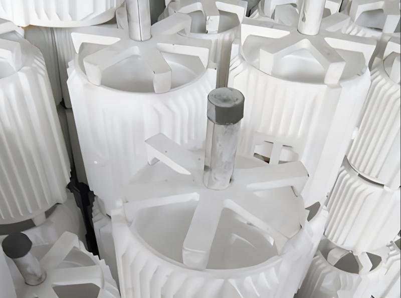
Wax Model Making
Once the CAD model is complete, a wax model can be made. The materials used for the wax model affect both cost and quality. A high-quality wax model allows for more precise and smooth parts. Poor material quality can lead to errors and increase workload. Draft angles help remove the wax model without damaging it. Insufficient draft angles can cause the wax model to crack or leave marks. KEMING uses a combination of traditional and modern methods to create wax models of complex shapes, achieving excellent results.
Casting Process Steps
The investment casting process involves several steps:
- Creating a wax model based on the 3D model.
- Applying molten ceramic to the wax model to create a mold.
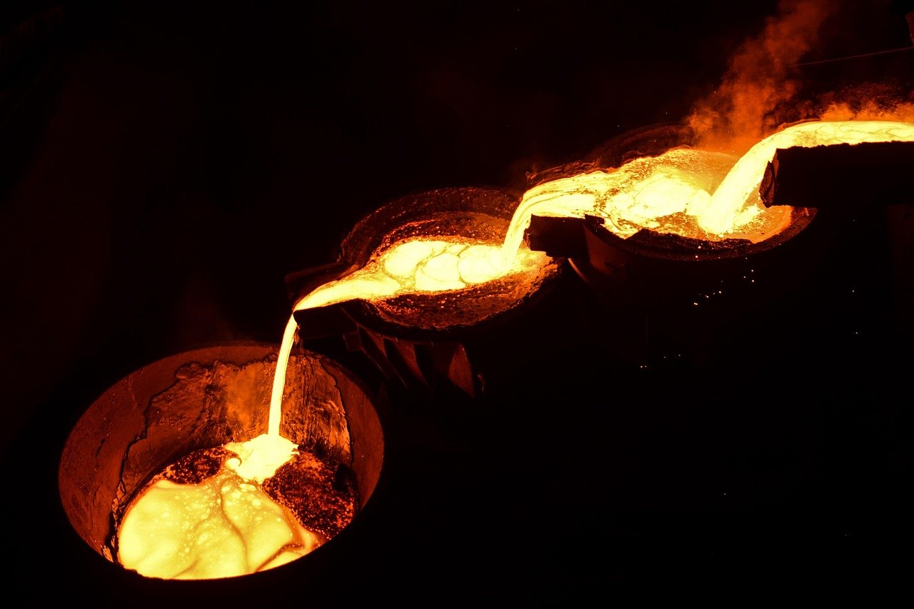
- Remove the wax model, leaving a hollow shell.
- Pour hot metal into the shell to form the part.
- Break the shell to complete the part’s construction.
Each step is crucial and contributes to the part’s shaping. Commin can adjust the process flow according to different sizes and shapes. The time required for each step varies:
| Stage | Duration |
|---|---|
| Tooling design | 4-6 weeks |
| Sample castings | 2-4 weeks |
| Production | 6-8 weeks |
Quality Control and Testing
Quality control inspection is crucial in precision casting. Commin employs testing methods such as X-rays, acoustic waves, and magnetic force to detect problems. These tests do not damage the parts. Aircraft and automotive parts require these tests to ensure safety and good performance. Most parts pass initial inspection, with yield rates exceeding 95% for orders with extremely high precision requirements. Commin’s rigorous inspections ensure that every part meets quality standards and can withstand a variety of demanding applications.
Note: When designers and foundries work together, the process flow is more streamlined, and part consistency is higher.
Considerations in Precision Casting
Material Selection
The metal you choose affects the performance and cost of the part. Engineers select metals based on the part’s function and operating environment. Precision casting can use a variety of metals. Some common choices include:
- MM247: This nickel-based superalloy is used to manufacture turbine blades and aircraft.
- R77, R80, R125: These nickel alloys offer heat resistance and rust resistance.
- U500: This high-strength nickel alloy is used to manufacture gas turbine blades.
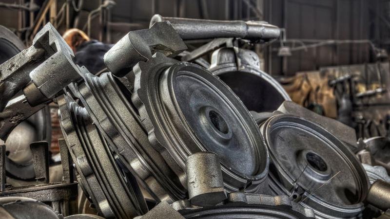
- Cast Iron: Ductile iron and gray cast iron offer good toughness and heat resistance.
- Copper Alloys: Used for piping, electrical components, and marine propellers.
- Superalloys: Cobalt and nickel are used in shipbuilding, chemical, and energy sectors.
- Carbon Steel: Requires careful selection of the appropriate alloy.
- Aluminum: Suitable for manufacturing multiple parts at once.
- Stainless Steel Alloys: Used for applications requiring rust protection.
- Brass: Chosen for its aesthetics and functionality.
Choosing the right metal ensures sufficient strength in the parts and also means less machining is required after casting. For example, 316 stainless steel can withstand temperatures up to 900°C.
Tolerances and Precision
Tolerances indicate how close a part is to its design values. Precision casting can produce very precise parts. Most parts have tolerance grades between CT5 and CT7. The table below shows common tolerances:
| Dimension Range (inches) | Tolerance (inches) | Approximate Tolerance (mm) |
|---|---|---|
| Up to 1″ | ±0.010″ | ±0.25 mm |
| Up to 2″ | ±0.013″ | ±0.38 mm |
| Up to 3″ | ±0.016″ | ±0.51 mm |
| Up to 4″ | ±0.019″ | ±0.64 mm |
| Up to 5″ | ±0.022″ | ±0.76 mm |
| Up to 6″ | ±0.025″ | ±0.81 mm |
| Up to 7″ | ±0.028″ | ±0.89 mm |
| Up to 8″ | ±0.031″ | ±0.96 mm |
| Up to 9″ | ±0.034″ | ±1.05 mm |
| Up to 10″ | ±0.037″ | ±1.19 mm |
| Over 10″ | ±0.005″ per inch | N/A |
Higher tolerances mean less cutting and less waste. Poor tolerances lead to more scrapped parts.
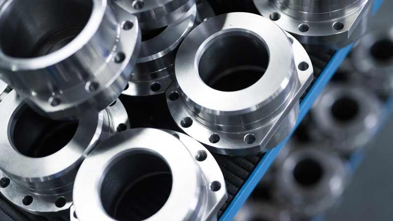
Complex Geometry
Investment casting can create shapes that are difficult to achieve using other methods. Designers can use thin walls, deep holes, and fine details. This is highly beneficial in many fields, such as aircraft and shipbuilding. More complex shapes may be more expensive, but they can create specialized parts. The KEMING team helps clients find the optimal balance between shape and manufacturing complexity.
Cost and Quantity Factors
The quantity and complexity of parts manufactured affect the price. The table below shows which method is better for different quantities:
| Production Volume | Better Choice | Reason |
|---|---|---|
| Low (< 5,000) | Investment Casting | Low tooling cost, higher part price |
| High (> 10,000) | Die Casting | High tooling cost, lower unit price |
Producing more parts reduces the price per part. The more complex the shape, the greater the machining volume and the higher the cost. Comming accepts orders of all sizes, giving customers more options.
Tip: Choosing the right metal, tolerances, and part quantity helps save costs and maintain high quality.
Designers achieve success in investment casting through simple steps. They select high-quality castings and use detailed molds. They choose the best mold for the job. The team creates 3D-printed molds for complex shapes. They carefully check each part to ensure it’s suitable for investment casting. Comming assists customers at every step. Experts help avoid mistakes and improve processes. Designers who follow these techniques obtain high-performance and durable parts.
FAQ
What is a mold in investment casting?
Molds determine the shape of the final part. They are used to create metal molds. Molds can be made from wax, plastic, or 3D-printed models. Many industries use molds to create strong and detailed parts. Molds help control the dimensions and surface of the finished product.
How do 3D-printed molds improve the manufacturing process?
3D printed molds make manufacturing processes faster and more flexible. Engineers can use them to quickly test designs. 3D printed molds reduce the need for expensive tooling. 3D printing solutions help businesses create complex shapes that are impossible with traditional molds.
Why do designers choose 3D printed casting molds?
Designers choose 3D printed casting molds to improve precision and speed. These molds facilitate small-batch production or prototyping. 3D printed casting molds also allow for design modifications without incurring additional costs. 3D printing solutions offer more options for creative shapes.
How do molds affect casting quality?
Molds control the detail and surface finish of castings. Good molds produce smooth surfaces and precise shapes. Poor molds lead to defects. Molds must fit the design closely. 3D printed molds and 3D printing solutions help improve quality by creating better molds.
Can 3D printing solutions help handle large-volume orders?
3D printing solutions are best suited for small-batch production or custom parts. For large-volume orders, traditional molds may be less expensive. 3D printed models still aid in testing and design modifications. 3D printing solutions can provide models that can accelerate production start-up.